



Looking for an AI CAD generator that can produce a part with exact dimensions, rather than just a convincing 3D render? Say you need a mounting plate with a centered hole. The first version is 60 mm long, but you later need to extend it to 80 mm without changing the width, thickness, or hole diameter.
That is the kind of task Text-to-CAD is built for. It is an open-source tool that works with AI coding agents such as Claude Code, Codex, and Cursor. The agent writes a parametric CAD model in Python, builds the geometry locally, and lets you revise the design through further instructions. Models can be exported to STEP, STL, 3MF, and other supported formats.
There is one important distinction: Text-to-CAD is not a browser-only text-to-3D service. It requires a local CAD runtime and a compatible AI agent. Its main appeal is the editable modeling workflow, not instant 3D artwork.

What Is Text-to-CAD, and How Is It Different From Other AI CAD Generators?
Text-to-CAD gives an AI coding agent the tools to create and modify CAD geometry. Instead of asking an image model to draw a part, you describe its dimensions, holes, and other features. The agent writes a Python script using build123d, which works with the Open CASCADE geometry kernel.
For example, you could request a small electronics enclosure with specific dimensions, mounting holes, and a removable lid. The agent can generate the model, open it in CAD Viewer, and revise the script when you change your requirements.
The project supports several agent environments, including Claude Code, Codex, Cursor, Gemini, and Grok. Integration details vary by agent.
What makes this different from many AI 3D generation tools is the underlying model definition. Text-to-CAD keeps the Python modeling script, so the agent can change dimensions or features and rebuild the geometry. You are not limited to editing a finished triangle mesh.
It does not replace the entire workflow of Fusion 360 or SolidWorks. Text-to-CAD primarily uses instructions and code to control a CAD model, rather than the full interactive feature-editing environment of a conventional CAD application.
The project is released under the MIT license. The CAD tooling is free to use, although your chosen AI agent or model provider may have separate subscription or API costs.
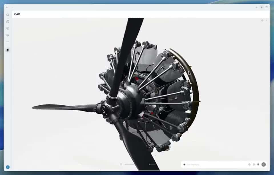
Why Parametric CAD Matters More Than a Good-Looking 3D Model
A 3D model can look right and still be unsuitable for manufacturing.
Consider a mounting plate measuring 60 × 25 × 6 mm, with an 8 mm through-hole at its center. If the length changes to 80 mm, the intended result is a longer plate with the same width, thickness, and hole diameter.
In a parametric workflow, those dimensions are defined in the model’s source code. Changing the length parameter and rebuilding the part is more predictable than stretching a mesh by eye.
Some text-to-3D services generate STL or OBJ meshes intended for visualization or 3D printing. Text-to-CAD instead uses solid geometry defined by build123d and can export a STEP file for use in other CAD applications.
There is an important limitation: an editable Python source model does not mean that an exported STEP file will preserve the original variables, construction history, or native feature tree.
STEP is useful for exchanging solid geometry. Whether the imported part can be edited parametrically depends on the receiving CAD software and its import workflow. If you need to maintain the original design logic, keep the Python script alongside the exported files.
How to Install Text-to-CAD for Codex or Claude Code
Text-to-CAD provides installation scripts for macOS, Linux, and Windows. The installer can detect supported agent applications, configure the necessary components, and register the cad command.
Because the installer may modify local application settings and install dependencies, it is worth reviewing the script before running it. The commands below download the installer first and use its dry-run option to preview the changes.
macOS and Linux
Download the official installation script:
curl -fsSL https://texttocad.dev/install.sh -o install.shReview install.sh in a text editor. Then preview an installation targeting Codex:
sh install.sh --dry-run --only codexIf the proposed changes look correct, install the integration:
sh install.sh --only codexTo install support for both Claude Code and Codex:
sh install.sh --only claude,codexYou can also disable the project’s optional usage telemetry during installation:
sh install.sh --only codex --no-telemetryRestart the affected agent applications after installation. The first launch may need an internet connection to download additional runtime components.
Windows
In PowerShell, download the installer without immediately executing it:
irm https://www.texttocad.dev/install.ps1 -OutFile install.ps1Inspect the downloaded file, then preview the installation:
powershell -ExecutionPolicy Bypass -File install.ps1 --dry-runFollow the official installation guide to select the appropriate options and complete the setup.
After installation, check the environment with:
cad doctor
cad status
If the terminal cannot find cad, check the installer’s output, your command path, and whether the agent needs to be restarted. Windows users may also need to review security prompts related to downloaded runtime components.
AI CAD Generator Example: Build a Mounting Plate From a Prompt
A simple mounting plate is a useful starting point. Its geometry is easy to understand, and the required dimensions can be checked without relying on how the model looks in the viewer.
Write a Prompt for Codex or Claude Code
After installing Text-to-CAD, give your agent a request such as:
Use the Text-to-CAD CAD Skill to create a parametric mounting plate. It should be 60 mm long, 25 mm wide, and 6 mm thick, with a centered 8 mm diameter through-hole. Use millimeters as the unit.
Save the Python model using build123d, build the geometry, and open it in CAD Viewer. Check the bounding dimensions and hole diameter using geometry inspection. Do not estimate dimensions from the preview image alone.
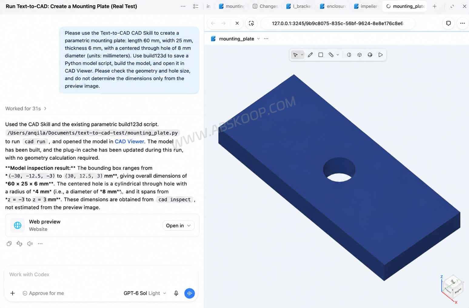
The agent should generate a Python model, run it using the local CAD environment, and open the result in CAD Viewer.
Here is a minimal example showing how the model can be defined. This code illustrates the documented Text-to-CAD modeling pattern; it is not presented as an independently benchmarked example.
import build123d as bd
from cad import model

LENGTH = 60
WIDTH = 25
THICKNESS = 6
HOLE_DIAMETER = 8

@model
def mounting_plate():
    plate = bd.Box(LENGTH, WIDTH, THICKNESS)
    hole = bd.Cylinder(
        HOLE_DIAMETER / 2,
        THICKNESS
    )
    result = plate - hole
    result.label = "mounting_plate"
    return result

if __name__ == "__main__":
    mounting_plate()
Assuming the script is saved as src/mounting_plate.py, build the model with:
cad run src/mounting_plate.pyA successful run should report the model’s identifier, bounding dimensions, and a local CAD Viewer URL. Record the model ID, since you will need it for inspection and export commands.
Text-to-CAD uses millimeters for its modeling units. The model’s actual dimensions should still be checked through the build output and geometry inspection.
Change the Length From 60 mm to 80 mm
Now suppose the plate needs to be longer, but nothing else should change.
Update the length parameter:
LENGTH = 80Then rebuild the model:
cad run src/mounting_plate.pyThe intended result is an 80 × 25 × 6 mm plate with the original 8 mm hole.
This is where geometry inspection matters. The viewer can show whether the plate looks longer, but it cannot by itself prove that the other dimensions stayed the same.
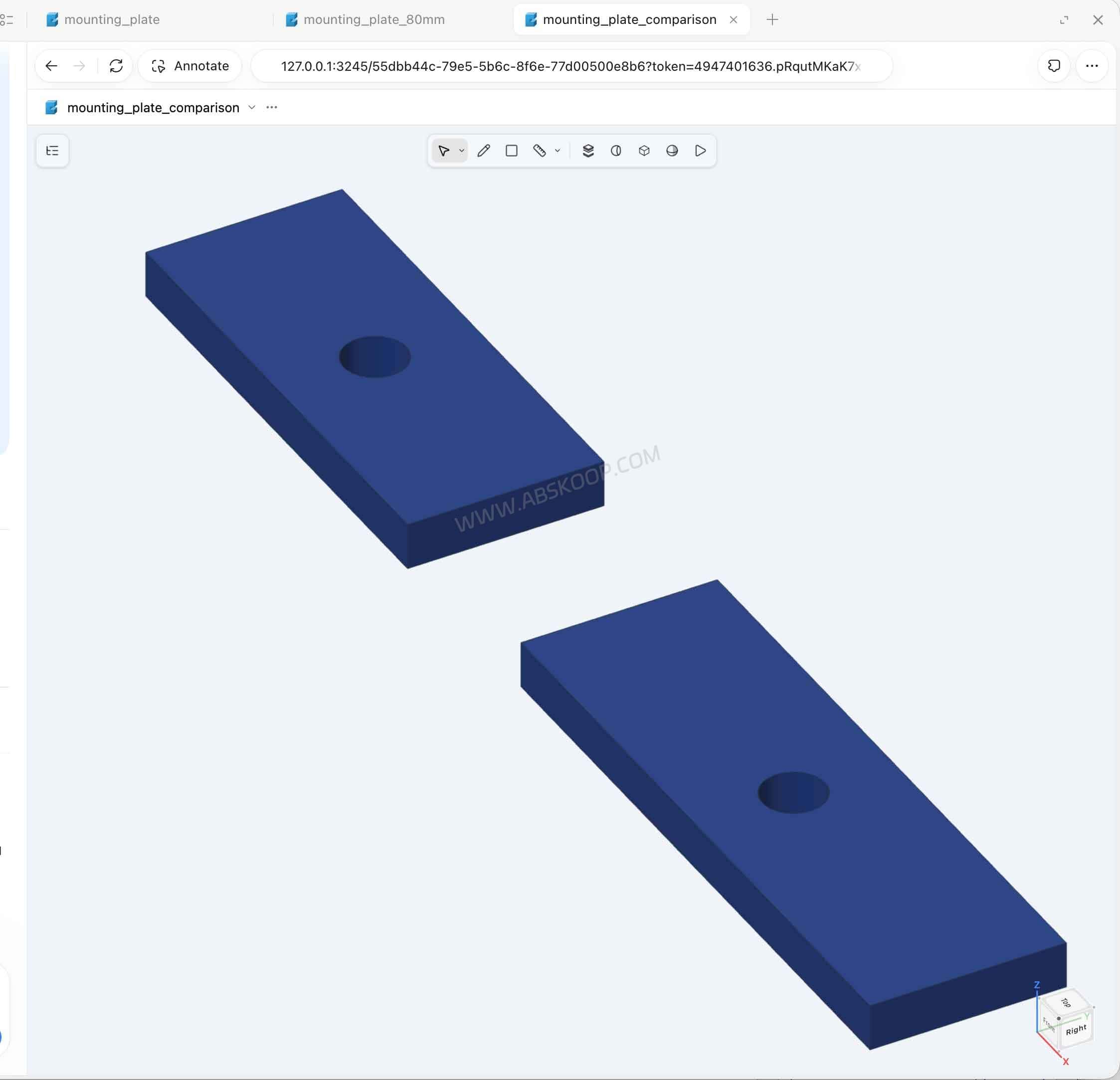
Check the model using cad inspect and, where necessary, a geometry-checking script. The bounding box should reflect the updated length, while the hole diameter and remaining dimensions should be verified separately.
According to the project’s documentation, the CAD runtime can reuse unchanged geometry calculations during a rebuild. This can reduce repeated work, but actual performance depends on the model and workload.
How to Export STEP, STL, 3MF and GLB Files
Text-to-CAD separates model construction from file export. Build the model first, obtain its ID, and then export the formats you need.
Replace MODEL_ID with the identifier returned by cad run:
cad export "MODEL_ID" STEP/mounting-plate.step STL/mounting-plate.stlYou can also export supported formats such as 3MF and GLB.
| Format | Typical use | What to check |
|---|---|---|
| STEP / STP | Exchanging solid geometry between CAD applications | Imported geometry may not retain the original parametric feature history |
| STL | Mesh-based 3D printing workflows | Scale, watertightness, wall thickness and tolerances |
| 3MF | Compatible 3D printing workflows | Compatibility with the target slicer and printer |
| GLB | 3D visualization and model presentation | Not a replacement for an editable mechanical CAD source model |
| XBF | Exchanging Text-to-CAD model documents | Not a universal replacement for a Python model script |
After exporting, reopen the STEP file in the CAD application you plan to use. Confirm the geometry, units, and dimensions rather than assuming the export is correct because the command completed successfully.
For 3D printing, load the STL or 3MF into your slicer and review the mesh, wall thickness, orientation, and print settings.
Keep the Python source script as well as the exported files. Updating the script does not automatically update an existing STEP or STL export. You must export the revised model again.
Beyond CAD Modeling: DFM Checks, Drawings and 3D Printing
Text-to-CAD also provides Skills for tasks that come after the initial model is created.
- DFM checks: Review design considerations for processes such as CNC machining, sheet metal fabrication, and injection molding.
- DfAM checks: Examine additive manufacturing considerations such as wall thickness, overhangs, support requirements, and build orientation.
- Engineering drawings: Generate dimensioned drawing PDFs with views and annotations.
- DXF and fabrication preparation: Create 2D profiles and prepare files for supported fabrication workflows.
- G-code and Bambu Lab workflows: Connect compatible slicing and printing tools to the CAD workflow.
These integrations can reduce the number of manual steps between modeling and manufacturing preparation. They do not remove the need for engineering review.
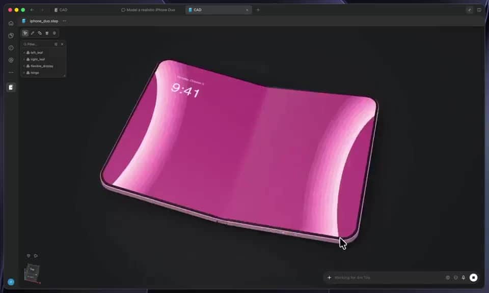
A completed CAD model, engineering drawing, or G-code file is not proof that a part is ready to manufacture. Load-bearing structures, critical fits, material behavior, safety requirements, and manufacturing tolerances still require appropriate checks.
Is Text-to-CAD Free, Open Source and Fully Local?
Text-to-CAD is free and open source under the MIT license. The CAD tooling does not require a separate software subscription.
However, Text-to-CAD relies on an AI agent to interpret your instructions and write the modeling script. If that agent uses a paid model or API, those costs are separate.
It is also important to distinguish local CAD processing from a fully offline workflow.
The CAD runtime operates on your computer. But if you use Claude Code, Codex, or another agent backed by a cloud model, your prompts and relevant project context may be processed by that model provider under its own terms.
According to the Text-to-CAD privacy policy, the project does not collect user prompts, models, drawings, or project files. Optional telemetry can include usage statistics and crash information and can be disabled.
For personal prototypes, the setup may be straightforward. For confidential product designs or customer CAD files, review both the Text-to-CAD runtime and the AI provider’s data-handling policies before using them together.
Who Should Use Text-to-CAD?
Text-to-CAD is worth considering if you already work with AI coding agents and need to create CAD parts with specific dimensions.
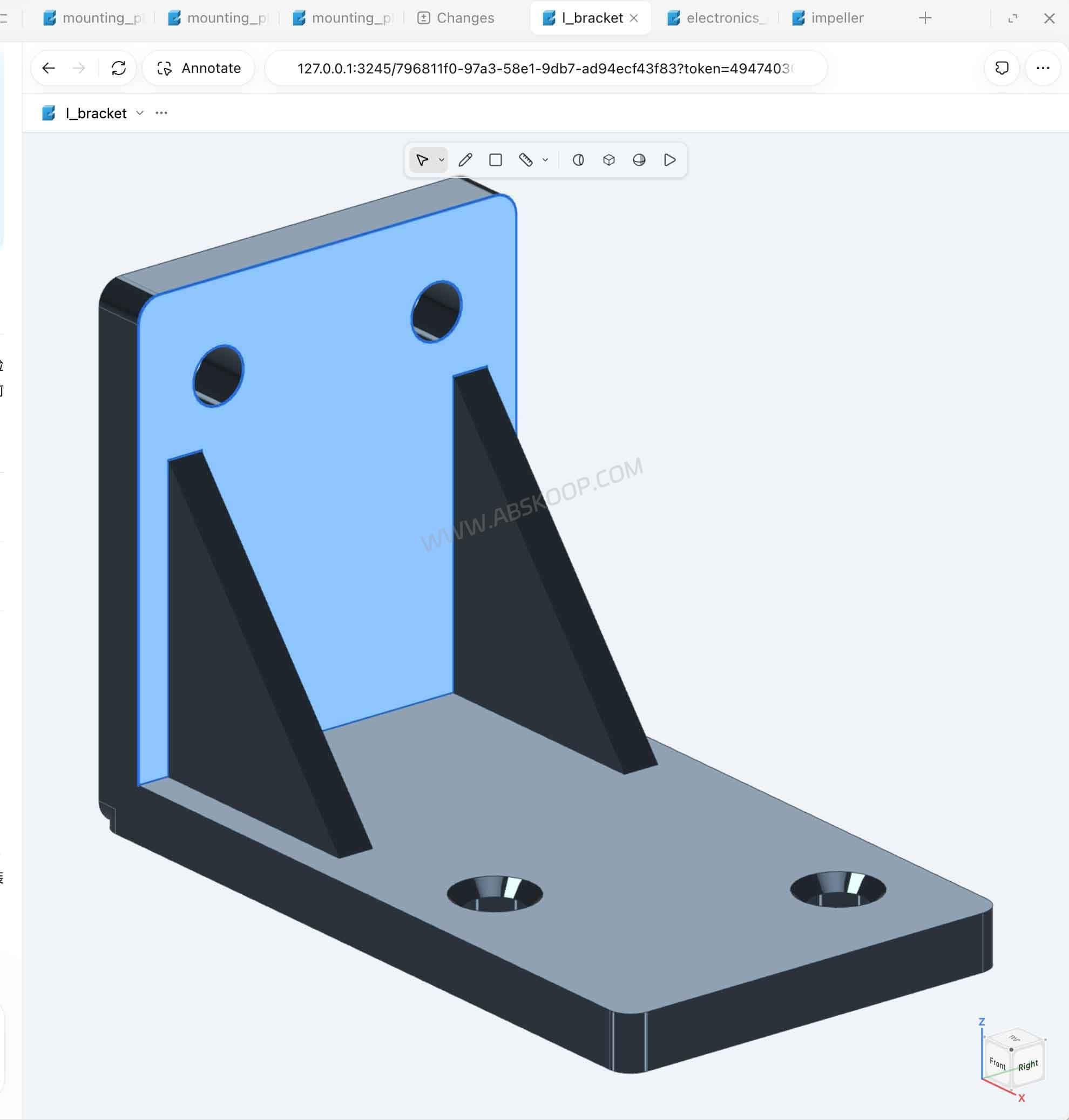
It is particularly relevant for developers, makers, and hardware prototyping workflows involving mounting brackets, enclosures, mechanical fixtures, and 3D-printable components.
On the other hand, it may not be the right choice if you want a browser-based tool that creates decorative 3D models with almost no setup.
It also cannot fully replace a conventional CAD package when your workflow depends on interactive feature editing, detailed assembly management, or mature engineering validation tools.
A practical way to evaluate Text-to-CAD is to start with one simple part. Generate the model, inspect the dimensions, change one parameter, export a STEP file, and reopen it in another CAD application. If you also plan to 3D print the part, check the STL in your slicer.
That exercise is more useful than judging the tool from polished model screenshots alone.
Frequently Asked Questions
Is Text-to-CAD a browser-based AI CAD generator?
Not primarily. Text-to-CAD integrates with compatible AI agents and uses a local CAD runtime to build models from Python scripts. It provides CAD Viewer for reviewing models, including through a browser when supported, but it is not simply a web form that converts text into 3D geometry.
Can I edit an exported STEP file in SolidWorks or Fusion 360?
You can use STEP to transfer supported solid geometry into compatible CAD applications. However, an imported STEP file may not contain the original Python variables or the receiving application’s native feature history. The editing options depend on the target software and import method.
Text-to-CAD Website, GitHub and Documentation
- Official website: Text-to-CAD
- GitHub repository: earthtojake/text-to-cad
- Installation guide: Official installation documentation
- CAD Skill: CAD modeling and inspection
- Privacy policy: Text-to-CAD privacy policy
If you are more interested in using AI agents to generate software architecture diagrams rather than mechanical CAD models, see our Archify overview. Both tools extend what coding agents can do, but they solve different problems.
Documentation checked: November 4, 2026. This article combines official documentation with supplied screenshots and public demonstrations. The installation-to-export workflow has not been independently validated end to end for this article. Specific commands and integration details may change between releases.


Comments (0)